概要
After power-on sequence or a system reset, the ARM® Cortex™-M4 processor fetches the top-of-stack value from address 0x0000 0000 and the base address of boot code from 0x0000 0004 in sequence. Then, it starts executing code from the base address of boot code.
Due to the selected boot source, either the main flash memory (original memory space beginning at 0x0800 0000) or the system memory (original memory space beginning at 0x1FFF F000) is aliased in the boot memory space which begins at the address 0x0000 0000.
When the on-chip SRAM, whose memory space is beginning at 0x2000 0000, is selected as the boot source, in the application initialization code, you have to relocate the vector table in SRAM using the NVIC exception table and offset register.
从以上摘取的文本可以看出,Cortex-M4内核在上电由硬件初始化后,将把0x0000 0000地址处的值设置为Stack Pointer (SP),然后跳转到0x0000 0004存储的地址,进而开始执行代码。(这一点和ARM9不一样,ARM9是直接执行0x0000 0000地址处的代码,因此第一条通常是跳转指令。)
以上启动步骤翻译成汇编代码如下:- ldr r0, =0x0
- mov sp, r0 // 也可以是 msr msp, r0
- ldr r0, =0x4
- bx r0
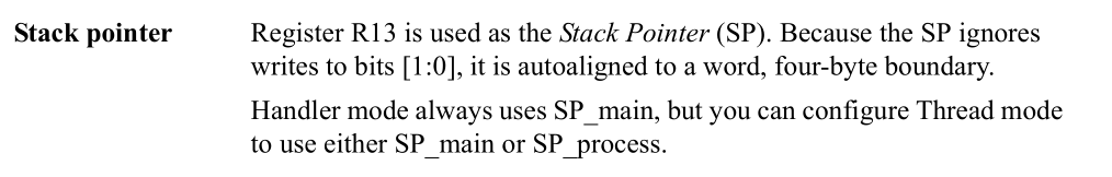
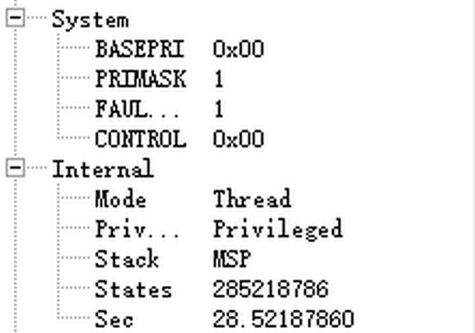
- 0x00000000地址处存放的SP值BIT[1:0]是无效的,将被自动4字节对齐(参考CortexM4_TRM_r0p1.pdf),Cortex-M4启动后,默认是特权模式下的Thread Mode且使用SP_main(MSP)。在裸机阶段,CONTROL的bit1始终是0,因此主循环(main)中断服务程序(xxx_Handler)都使用MSP,PSP不起作用。
- Cortex-M4处理器指令是16位对齐的,因此PC寄存器的BIT[0]也是无效的,自动2字节对齐。

但Cortex-M4仅支持thumb/thumb2指令集,使用跳转指令时,目标地址的BIT[0]需要置1,表明目标分支处于thumb程序区域,因此0x00000004地址处存放的跳转地址BIT[0]必须是1(在反汇编时候,需要忽略跳转指令目标地址的最低位)。
ARM跳转指令格式:B{条件} 目标地址,结合不同的条件位,可以变成BX: 带状态切换的跳转,BLX: 带链接和状态切换的跳转。由于BX和BLX指令使用目标地址的BIT[0]推算出目标状态,可将处理器的状态从ARM更改为thumb,或从thumb更改为ARM,如果目标地址的BIT[0]为0,则处理器的状态会切换到ARM状态;如果目标地址的BIT[0]为1,则处理器的状态会切换到thumb状态。
- 参考文档ARM-AAPCS-EABI-v2.08.pdf CortexM4_TRM_r0p1.pdf
由于各类MCU支持不同的启动方式,因此内核启动的0地址将会被映射到不同的其它地址,这种启动方式的切换通常使用一些GPIO进行配置。
以某款国产Cortex-M4 MCU为例,下面将列出不同启动方式下,SP和Reset Code的取值地址:
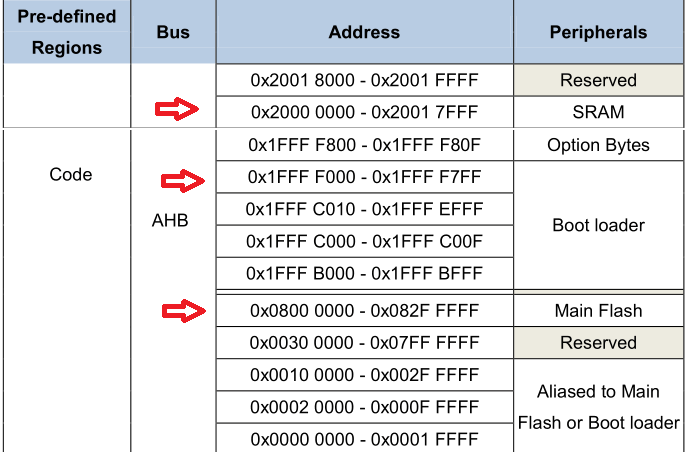
启动方式SP取值地址PC取值地址Flash0x080000000x08000004SRAM0x200000000x20000004BOOTROM0x1FFFF0000x1FFFF004不过由于这种由启动方式不同导致的地址映射关系改变是由芯片内部处理的,因此在最终生成的bin文件中,SP和PC依旧被放在相对文件的0地址和4字节地址偏移处;这种0地址的映射只是便于在上电时可以使用不同的启动介质,当内核通过某一介质启动后,完全可以切换到其它地址空间运行;例如通过GPIO配置为Flash启动一个stubloader,启动完成后将bootloader从某个其它的介质加载到SRAM,然后修改SP和PC地址,实现切换到SRAM运行。
示例分析
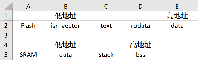
这里给出的用于示例分析的连接脚本和启动文件,只需这两个文件即可构建出用于启动的bin文件。- /* 因为下面.isr_vector节中配置为KEEP(*(.isr_vector)),表明保持isr_vector节信息不变原样输出 */
- /* 这里指定程序入口点(ENTRY)对于裸机环境是无意义的(除非使用了标准库的启动代码,例如crt0),放在这里主要起辅助阅读作用 */
- ENTRY(Reset_Handler)
- /* c栈大小 */
- _system_stack_size = 0x200;
- /* Specify the memory areas */
- MEMORY
- {
- FLASH (rx) : ORIGIN = 0x08000000, LENGTH = 4K
- RAM (xrw) : ORIGIN = 0x20000000, LENGTH = 4K
- }
- /* Define output sections */
- SECTIONS
- {
- /* 这里首先存放启动代码到Flash,KEEP(*(.isr_vector))表示保持isr_vector段的数据不变直接输出,isr_vector段信息将在startup.S启动文件中定义 */
- .isr_vector :
- {
- . = ALIGN(4);
- KEEP(*(.isr_vector)) /* Startup code */
- . = ALIGN(4);
- } >FLASH
- /* 代码和一些常量与常量字符串 */
- .text :
- {
- . = ALIGN(4);
- *(.text) /* .text sections (code) */
- *(.text*) /* .text* sections (code) */
- *(.rodata) /* .rodata sections (constants, strings, etc.) */
- *(.rodata*) /* .rodata* sections (constants, strings, etc.) */
- *(.glue_7) /* glue arm to thumb code */
- *(.glue_7t) /* glue thumb to arm code */
- *(.gnu.linkonce.t*)
-
- KEEP (*(.init))
- KEEP (*(.fini))
- . = ALIGN(4);
- _etext = .; /* define a global symbols at end of code */
- } >FLASH
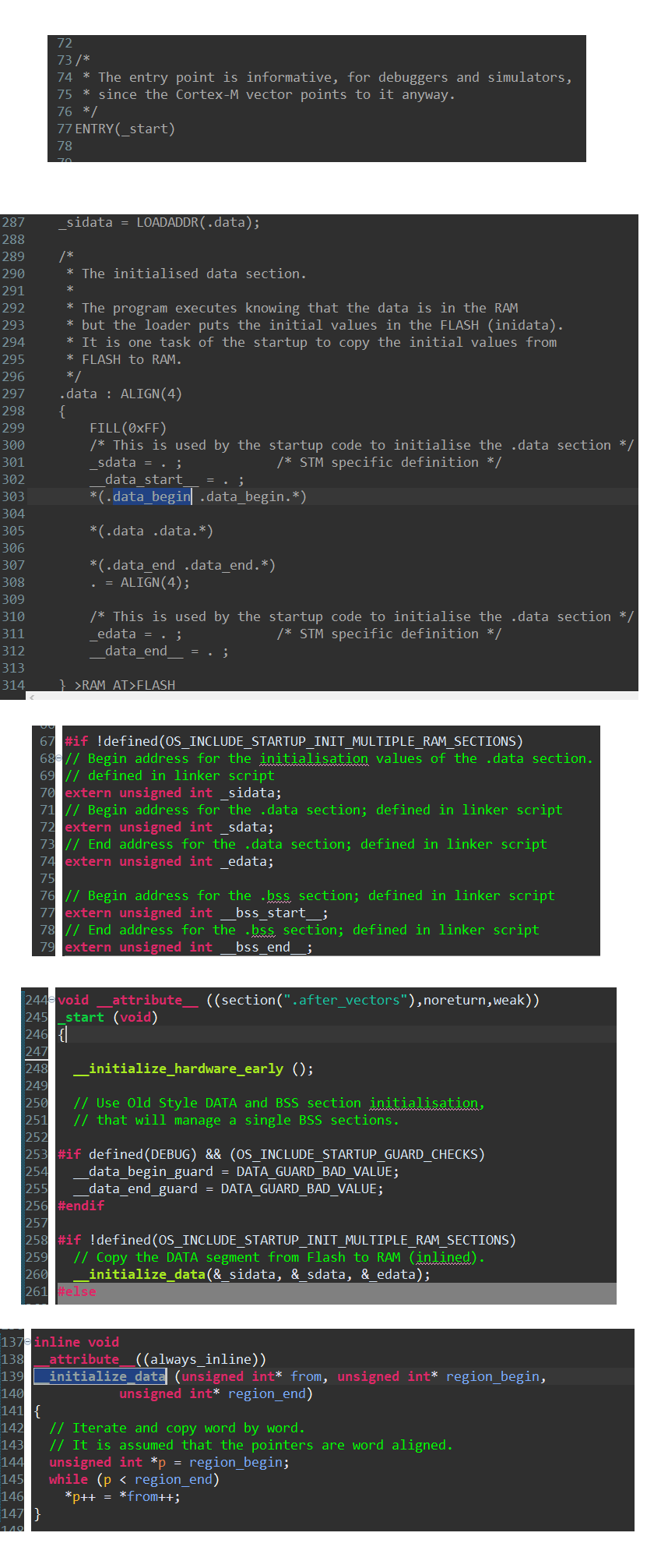
- /* used by the startup to initialize data */
- _sidata = .;
- /* Initialized data sections goes into RAM, load LMA copy after code */
- /* 这里data段会放入Flash地址空间并在RAM地址空间预留相同空间,上电后由启动代码复制到到RAM。AT ( _sidata )另一种写法是在段结束处 " >RAM" 改成 " >RAM AT> FLASH" */
- /* 如果bin文件是加载到RAM运行的,data段只会在RAM地址空间有一份,启动代码就无需"copy data section" */
- .data : AT ( _sidata )
- {
- . = ALIGN(4);
- _sdata = .; /* create a global symbol at data start */
- *(.data) /* .data sections */
- *(.data*) /* .data* sections */
- *(.gnu.linkonce.d*)
-
- . = ALIGN(4);
- _edata = .; /* define a global symbol at data end */
- } >RAM
-
- /* 栈可以放在bss前面或后面,ARM-Thumb过程调用标准和ARM、Thumb C/C++编译器总是使用满递减栈,只需要保证向低地址方向有足够空间即可*/
- .stack :
- {
- . = ALIGN(4);
- _sstack = .;
- . = . + _system_stack_size;
- . = ALIGN(4);
- _estack = .;
- } >RAM
- /* 未初始化或者初始化为0值的全局变量,只需要在RAM中留出空间,启动代码中清零即可 */
- __bss_start = .;
- .bss :
- {
- . = ALIGN(4);
- /* This is used by the startup in order to initialize the .bss secion */
- _sbss = .;
-
- *(.bss)
- *(.bss.*)
- *(COMMON)
-
- . = ALIGN(4);
- /* This is used by the startup in order to initialize the .bss secion */
- _ebss = . ;
-
- *(.bss.init)
- } > RAM
- __bss_end = .;
- _end = .;
- /* 后面省略了移除标准库中调试信息节的声明 */
- }
启动文件
复位后关闭中断和异常(内核中断),复制data section,清零bss section,最后后进入死循环。- .syntax unified
- .cpu cortex-m4
- .thumb
- .global g_pfnVectors
- .global Default_Handler
- /* start address for the initialization values of the .data section.
- defined in linker script */
- .word _sidata
- /* start address for the .data section. defined in linker script */
- .word _sdata
- /* end address for the .data section. defined in linker script */
- .word _edata
- /* start address for the .bss section. defined in linker script */
- .word _sbss
- /* end address for the .bss section. defined in linker script */
- .word _ebss
- /* stack top(Full descending). defined in linker script */
- // .word _estack
- .section .text.Reset_Handler
- .weak Reset_Handler
- .type Reset_Handler, %function
- Reset_Handler:
- /* set stack pointer */
- // no need for cortex-m4
- // ldr r0, =_estack
- // mov sp, r0
- /* Disable IRQ and FIQ*/
- cpsid i
- cpsid f
- /* Copy the data segment initializers from flash to SRAM */
- movs r1, #0
- b LoopCopyDataInit
- CopyDataInit:
- ldr r3, =_sidata
- ldr r3, [r3, r1]
- str r3, [r0, r1]
- adds r1, r1, #4
-
- LoopCopyDataInit:
- ldr r0, =_sdata
- ldr r3, =_edata
- adds r2, r0, r1
- cmp r2, r3
- bcc CopyDataInit
- ldr r2, =_sbss
- b LoopFillZerobss
- /* Zero fill the bss segment. */
- FillZerobss:
- movs r3, #0
- str r3, [r2], #4
-
- LoopFillZerobss:
- ldr r3, = _ebss
- cmp r2, r3
- bcc FillZerobss
- MainLoop:
- b MainLoop
- .size Reset_Handler, .-Reset_Handler
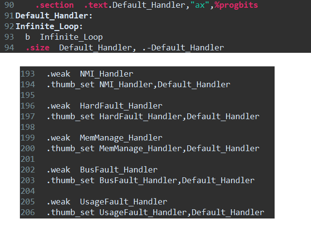
- .section .text.Default_Handler,"ax",%progbits
- Default_Handler:
- Infinite_Loop:
- b Infinite_Loop
- .size Default_Handler, .-Default_Handler
- .section .isr_vector,"a",%progbits
- .type g_pfnVectors, %object
- .size g_pfnVectors, .-g_pfnVectors
-
- g_pfnVectors:
- .word _estack // Top of Stack
- .word Reset_Handler // Reset Handler
- .word NMI_Handler // NMI Handler
- .word HardFault_Handler // Hard Fault Handler
- .word MemManage_Handler // MPU Fault Handler
- .word BusFault_Handler // Bus Fault Handler
- .word UsageFault_Handler // Usage Fault Handler
- .word 0 // Reserved
- .word 0 // Reserved
- .word 0 // Reserved
- .word 0 // Reserved
- .word SVC_Handler // SVCall Handler
- .word DebugMon_Handler // Debug Monitor Handler
- .word 0 // Reserved
- .word PendSV_Handler // PendSV Handler
- .word SysTick_Handler // SysTick Handler
- // external interrupts handler
- .word WWDGT_IRQHandler // 16:Window Watchdog Timer
- .word LVD_IRQHandler // 17:LVD through EXTI Line detect
- .word TAMPER_IRQHandler // 18:Tamper through EXTI Line detect
- .word RTC_IRQHandler // 19:RTC through EXTI Line
- /* 省略其他中断入口地址...*/
- -mcpu=cortex-m4 -march=armv7e-m -mthumb -mlittle-endian -mfloat-abi=soft -mno-unaligned-access -O0 -fmessage-length=0 -fsigned-char -ffunction-sections -fdata-sections -Wuninitialized -Wall -Wpointer-arith -Wshadow -Wlogical-op -Waggregate-return -Wfloat-equal
- -mcpu=cortex-m4 -march=armv7e-m -mthumb -mlittle-endian -mfloat-abi=soft -nostartfiles -Xlinker --gc-sections
- Invoking: GNU Arm Cross Print Size
- arm-none-eabi-size --format=berkeley "app.elf"
- text data bss dec hex filename
- 372 0 512 884 374 app.elf
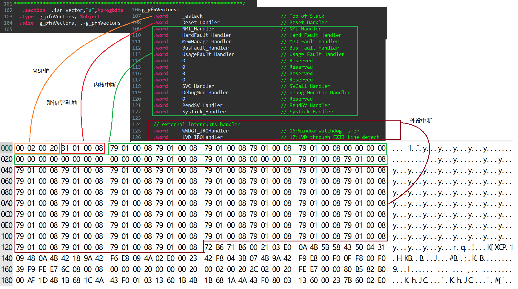
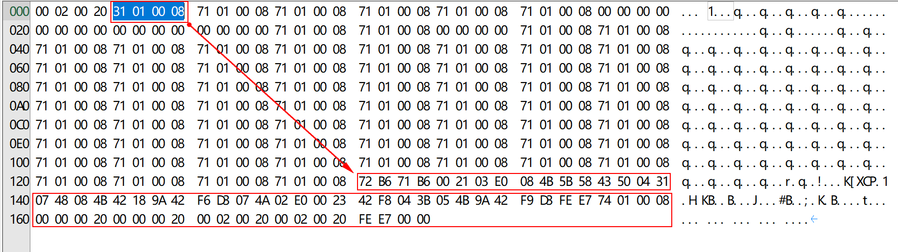
MSP = 0x20000200:
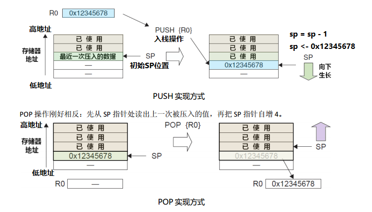
从上文的编译输出可以看到,data区占用0字节,因此只有c栈使用RAM空间,那么它的地址范围就是0x20000200~0x00000000;Cortex-M4使用的是满减栈模型。堆栈指针SP指向一个被压入堆栈的32位数值。在下一次压栈时,SP先自减4,再存入新的数值,因此虽然在连接脚本设置的栈大小是512字节,实际上只能用到508字节,栈顶最高4字节会空着。
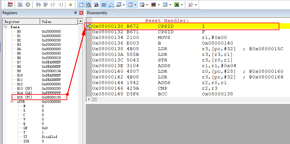
在线调试看出SP寄存器值与bin文件一致:
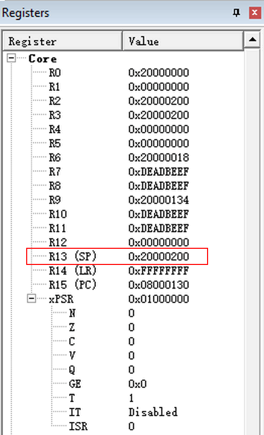
PC = 0x08000130
bin文件的4字节偏移处存放跳转地址,由于是thumb指令,实际的PC值需要将最低字节清零0x08000131 & 0xFFFFFFFE = 0x08000130。
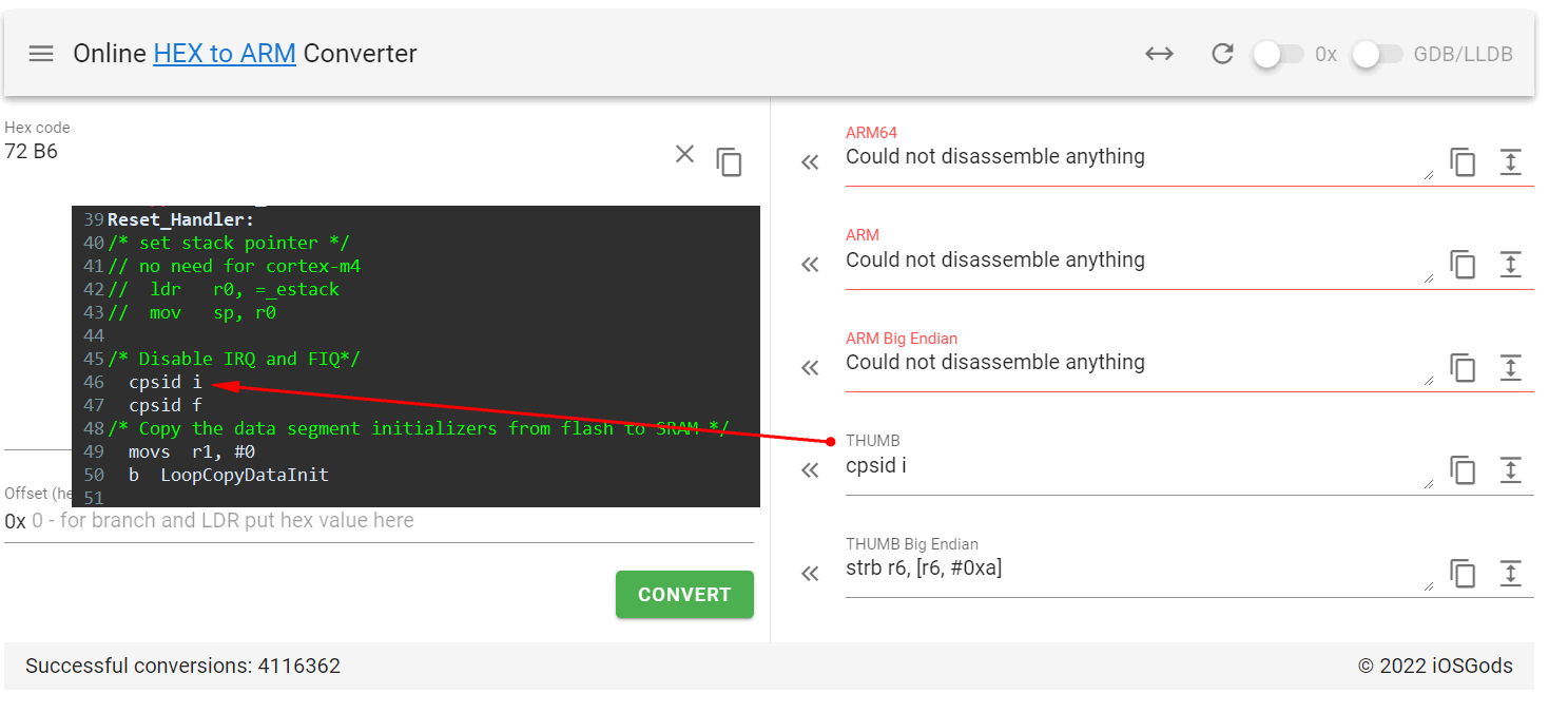
这里也可以将指令复制下来,填入一个在线ARM Code转汇编的网站:https://armconverter.com/
thumb指令只需要复制2字节就可以,可以看到反汇编结果与编写的代码一致。
总结
ARM的裸机启动过程还是比较简单的,设置好PC就可以运行在汇编环境,再设置SP值就可以有寄存器的入栈和出栈(c语言的函数调用时保存当前的寄存器值),只有这两步是必须在汇编环境下操作,后续的copy data 和 clear bss也可以使用c语言进行,例如newlib中的startup.c。
附录:
Arm® Cortex®-M4 Processor Technical Reference Manual Revision r0p1:
https://developer.arm.com/documentation/100166/0001/
Arm Cortex-M4 Processor Datasheet:
https://developer.arm.com/documentation/102832/latest/
ARM-software/abi-aa:
https://github.com/ARM-software/abi-aa/releases
在线ARM机器码转汇编或ARM汇编转ARM机器码:
https://armconverter.com/
免责声明:如果侵犯了您的权益,请联系站长,我们会及时删除侵权内容,谢谢合作! |